| Click on the thumbnail to maximize the image |
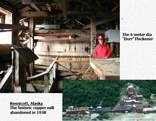
| Description Conventional Thickeners are generally incorporated in heavy duty applications when the underflow density is high and substantial torques are required to convey the settled solids from the periphery to the central outlet for pumping away. Likewise, thickeners are often used for storage to facilitate the continuous feeding of downstream filters or centrifuges. Historically thickeners were introduced to the mining industry in 1905 when the beneficiation of ores by froth flotation was invented in Australia. In 1964 there was a project to reprocess the huge piles of tailings that accumulated over the years and recover the remaining copper . At that time I was employed by Eimco in Salt Lake City, Utah and participated in a team that conducted test work checking the suitability of large diameter thickeners for both concentrate and tailings of the reprocessed ore. The picture on the right shows a 6 meter diameter wooden tank "Dorr" thickener installed back in 1908 in the Kennicott Copper Mill in McCarthy, Alaska and in 2011 I had the thrilling opportunity to fly from Chitina to McCarthy in a six seater plane to visit the abandoned mill.
|
 |
Basically there are two groups of thickeners which differ in their rake driving mechanisms:
The following tree shows the two main thickener groups and their various configurations:
There are two methods of supporting the heavy drive with its shaft and raking arms:
In the bridge type a structure spans across the tank and is subjected vertically to the weight of the mechanism plus any solids that accumulate within the arms truss and horizontally to the twin forces imposed by the density of the raked underflow.
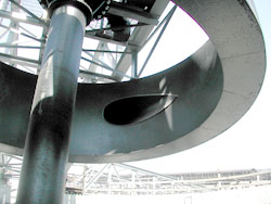
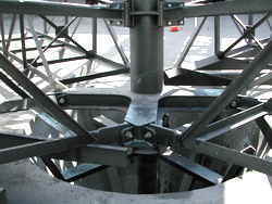
In the column type a central steel or concrete column takes vertically the reaction to the weight of the mechanism and horizontally the torque load.
There is a rule of thumb as to the break even between bridge type and column type mechanisms. For tanks up to 25-30 meter diameter the former type is selected and for larger diameters the later type. However, in many instances other considerations determine the selection such as the local cost of steel versus concrete. Also selection may be influenced by process consideration such as the handling of the dense underflow through a central discharge cone, as in the bridge type, or in a circular trough as in the column type thickeners.
The drive head, together with the raking arms, are the heart of the mechanism since the entire operation of the thickener depends on their ability to convey continuously the dense underflows from the periphery of the tank to the center. Hence, they are always of a robust design to meet the most difficult duties such as metallurgical, potash or phosphate applications where densities may reach 55-60% solids by weight.
Another important factor is reliability since unlike many other types of equipment, thickeners have no stand-bys so if one goes out of commission it cannot be by-passed. Consequently, if this happens other thickeners have to take the extra load but if the plant incorporates just one thickener then the entire production line must stop. Likewise, to take a thickener out of commission for internal repairs such as repair of damaged blades, or rubber lining may take days since it requires to empty the tank, wash out with hoses the underflow bed, refill the tank and find a suitable storage or disposal site for the very large volumes of liquid.
|
The majority of the drive heads are mechanically driven however hydraulically driven units are also in use.
Typical bridge type drive heads for small thickeners consist of a worm gear as shown on top and for larger units spur gears as may be seen at the bottom. The drives are always mounted directly on the bridge. |
The drive head below is designed for column type thickeners. The main gear consists of a rim with internally machined teeth so that the space in the center is left free for a post that is bolted to the top of the column and supports the walkway. It should be noted that the structure that spans radially on a column type thickener is not subjected to any operational load and serves merely as the inner support for the walkway.
To view the components
move the mouse pointer over menu
|
|
 |
Drive heads for both bridge and column type thickeners may be driven by up to 4 electric motors of hi-slip design which can reach 5-8 percent slip without loss of power nor overheating. This special design is required to ensure that the load on the main gear is balanced so that each primary reducer, and subsequently the entire reduction train, is subjected to an equal strain.
The torque capability of a thickener drive is specified as Duty Rating being the maximum mechanism design strength or the 100% setting on the Torque Control Box. The torque, in turn, depends on a K factor and the thickener diameter based on the following formula:
Torque (in Nm) = 14.6*K*D2 (in meters)
The following table specifies the K factors for different Duty Ratings:
| Machine Duty | K Factor |
| Light | 3-7 |
| Medium | 7-12 |
| Standard | 12-19 |
| Heavy | 19-20 |
| Extra Heavy | 21-40 |
In general terms the type of thickener and its drive torque rating ranges between the following values:
| Type of Thickener Drive | Torque Rating |
| Bridge with Worm Gear Drive | 3000-140000 Nm |
| Bridge with Spur Gear Drive | 20000-1440000 Nm |
| Column with Spur Gear Drive | 27000-3270000 Nm |
The Lifting Device and Torque Control
The lifting device is the element that raises and lowers the raking arms during operation so that the blades follow the interface of the settled solids by monitoring the torque. This ensures that the torque is maintained within set limits so that the arms are raised when the torque increases or lowered when the torque decreases. The control box is mounted on the primary reducer and generally contains 4 microswitches set to the following sequence:
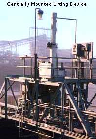
There are two types of lifting devices for bridge type thickeners:
Small and medium diameter thickeners will normally incorporate a Centrally Mounted Lifting Device supported by the drive head that is fixed to the bridge structure. A screw is attached to the shaft of the raking arms which are raised or lowered depending on the monitored torque. The power to the rotating lifting motor and its control from the microswitches is supplied by a slip ring housing that is stationary and mounted on the lifting screw cover.
 |
|
Also column thickeners have two types of lifting devices:
The Telescopic Cage type where the drive head remains stationary on the column. This device consists of
two cages, an internal cage that is bolted to the rotating drive rim to transmit the torque and an external cage that is raised together with the raking arm by 4 screws driven by a chain and sprockets.
The Telescopic Column where the drive head is mounted on a base so that both are raised or lowered by two screws that are actuated by an electric motor from an upper platform. The torque is transmitted to the raking arms by the reaction between the telescopic column and the main column.
The lifting height of the raking arms depends largely on the application and can vary from 30 cm for feeds with a steady slurry inflow up to 120 cm for thickeners that facilitate storage.
The duty of the raking arms is to convey the settled solids from the entire area to the discharge cone of bridge type thickeners or the circumferential trough that surrounds the column of column type thickeners.
The are two configurations of raking arms:
The difference is in the number of times that the tank floor is raked.
 |
In this arrangement and when the volume of solids to be conveyed is low there are two long arms and the blades of each arm overlap so they move the solids twice per revolution. |
 |
In this arrangement and when the volume of solids to be conveyed is high two short arms are added in 90 degrees to the two long arms so that the inner circle of the thickener's floor is raked four times per revolution. Rarely also six short arms in 30 and 60 degrees are added to the long arms and rake the inner circle of tank floor six times per revolution. |
On light duty applications straight blades are used however curved blades are always attached to arms that are designed for heavy duty applications. On certain heavy duty applications with thixotropic slimes the blades are not directly attached to the arm truss but connected through posts to avoid an effect called "doughnutting" in which the entire mass of solids rotates without being conveyed to the center. The thixo blades as they channel through the slime help in reducing this effect and promote the release of liquid to increase the density of the underflow.
On abrasive applications the rakes and blades are subjected to a significant wear so it is good practice to increase their thickness for corrosion allowance.
The Scum Skimmer
|
On some applications, such as thickening downstream froth flotation, a thick scum layer floats on the surface of the liquid. This layer finds its way into the overflow launder and contaminates the clear overflowing liquid with fines. This problem is solved by incorporating a scum baffle that retains the scum layer so that a special rotating scum skimmer pushes the scum into a box for disposal. |
Thickener tanks may be constructed either from steel or concrete and may reach diameters of 120 meters and in earthen basins up to 180 meters. Most of the chemical process industries prefer the steel tanks construction since they may be elevated above ground level, allow inspection of the tank's floor for leakages and bring the underflow slurry pumps nearer to the outlet of the discharge cone. Another consideration in selecting steel tanks is their ready adaptation to corrosive processes by rubber covering the wetted parts of the tank.
The bottom of the tanks are sloped and on smaller thickeners there is one continuous slope of 13/4:12. On larger thickeners there are normally two slopes with the external circle at 1:12 and the internal 2:12. The discharge cone's slope is always 1:1.

A great deal of engineering was done on elevated tanks to optimize floor design for steel weight to vertical load ratio and the density of the supporting structure. For many years the floor was constructed of flat steel plates cut in sectors to form the round shape of the thickener's bottom. In this design the each sector was subjected circumferentially to bending stresses and required sufficient thickness to take the vertical load. In the mid 60's the Japanese have proposed for an Alumina Plant in Queensland to form shelled sectors in a Catenary curve that resemble power lines. This curve subjects the sectors to tension without bending and results in a substantial saving in floor weight.
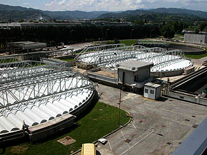 |
Roofs that cover the entire tank are sometimes used for process conditions that require to preserve slurry temperature or to avoid the hazard of corrosive gases emitting from the surface. Such roofs are usually made from fiberglass plates that are supported in the outer circumference by the tank's wall and internally by the bridge. A hydraulic inverted cup seal between the central shaft and the roof ensures that no gases are leaving to the atmosphere. For thickeners with lifting devices the seal should by long enough to retain the gases regardless of the arms position. In another technique that saves the cost of the roof plastic balls are spread to float on the surface to preserve heat but its efficiency is low. The problem with roofs is that special covers on the circumference of the roof are required for accessing the overflow weir and launder periodic cleaning. Likewise, the roof must be strong enough to carry the maintenance personnel.
|
The overflow weir that surrounds the tank ensures that the flow that leaves the thickener is distributed evenly in terms of m3/hr/m weir length. During the first year or so differential settling of the tank foundations may cause an uneven distribution so that the entire flow passes over the lower part of the weir which results in high velocities and drag of fines to the overflow launder. Therefore, it is essential to check from time to time that the weirs are in leveled.
Two of the most common overflow weirs are illustrated on the right and show the adjustable leveling clamps. The "V" notch weir is generally more common since the triangular notches are not so sensitive to slight deviations in the level of the tank.
The Feedwell
 |
 |
The purpose of the feedwell is to dampen the turbulence of the incoming feed so that the entry into the thickener will be as laminar as possible and will not interfere with the solids that are already settling inside the tank. This effect is achieved by entering the feedwell tangentially so that the centrifugal swirl distributes the feed in an even pattern below the liquid level.
It is good practice to connect the tangential pipe so that the introduced stream swirls in an opposite direction to the rotation of the raking arm. This will reduce the risk that slow settling solids may "doughnut" as described in the section on the raking arms.
The Cone Scraper
Pumping of dense underflows has always been a problem on thickeners that handle slurries such as metallurgical concentrates, potash or phosphate and the position of the pumps in relation to the discharge cone can be very critical. The principle is to position the slurry pumps so that their suction side will be as close as possible to the cone's outlet and it is also good practice to have two pumps, one in operation and one as stand-by.
There are three ways of positioning the pumps:
For bridge type thickeners with tanks that are elevated above ground level the positioning is simple since the cone is freely accessible.
For bridge and column type thickeners with tanks that are mounted on ground level the access to the slurry pumps is trough a tunnel.
For very large column type thickeners the column is constructed as a caisson that is submerged in the slurry so that the pumps are housed at the bottom of the chamber and deliver the underflow upwards.
For small thickeners, which are normally of the bridge type, the pumps are positioned at the periphery of the tank and the suction pipe is buried or runs through a pipe sleeve for replacement if necessary.
The Peripheral Drive Mechanisms
These thickeners incorporate a central column that serves as a pivot to a rotating raking arm that spans radially towards the periphery of the tank. The outer end of the arm has a carriage with motorized wheels that are guided by a circumferential track and move the entire arm structure in a circular trajectory to convey the settled solids towards the center. The bridge is not subjected to any operational loads and serves merely as a walkway for accessing the column and its pivot point from the outside.
Traction thickeners have no lifting devices therefore they cannot be used for storage.