|
Click on the
thumbnail to maximize the image |
Description
Horizontal Belt Filters are, in broad terms, the most commonly used vacuum
filters in the industry due to their flexibility of operation, adaptation to
corrosive slurries and suitability to handle large throughputs.
The
development of the Horizontal Belt Filters for the chemical process industries
was closely associated with the progress in rubber technology since they
incorporate an endless and thick rubber belt of a complex design to support the
cake retained by the filter cloth.
The first known filters were the
Landskrona and Lurgi built in the 20's and the Giorgini which was a belt filter
but with attached trays. The belts were very narrow and short, with a 30 cm wide
by 4-5 meters length, and were primarily applied to the washing of phosphate
rock. Later, being top feed filters that facilitated multi-washing stages, they
were applied in phosphoric acid plants to replace the chains of 3 or 4 internal
feed rubber covered Drum Filters used for gypsum washing. As the demand for area
has gone up filters were manufactured with three and four 30 cm wide belts
running in parallel since the rubber manufacturers were unable to catch-up with
the growth of the chemical plants. For this reason the main rivals over the
years to belt filters were the Tilting Pan and
Table Filters so when rubber belts were the
constraint to filtration area growth these filters were in demand and vice
versa. Nowadays it is high time for belt filters since rubber technology has
made a big step forwards in the past 10 years. Belts 4 meter wide for 120 m2
filters weigh more than 10 ton and are manufactured in one piece from
sophisticated rubber compounds.
Belt speed is another parameter that sets forth a race among the designers of filters since for many applications a short cycle time is essential. The constraining factor on belt speed is purely mechanical and depends largely on the supporting method of the heavy belt with its cake on it. Belt filters are the fastest filters available today and the speed of modern filters can reach over 50 m/min and yield very short cycle times.
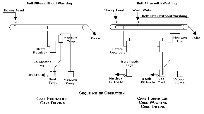
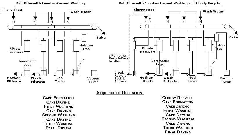
Typical flowschemes and their operating sequence is shown below:
|
Belt Filter without Washing This shows a basic flowsheet existing in all applications that require straight forwards dewatering. In these applications the objective is to produce a cake with the lowest moisture and there is no importance that remaining liquid in the cake retains its original quality. Belt Filter with Washing This flowsheet shows the addition of a cake washing stage at some point downstream cake formation. In this application water, or any other wash liquid, is used to displace the mother liquid whenever the process requires a cake that is free of substances that contaminate the discharged cake. |
|
|
Belt Filter with Counter-Current Washing This flowsheet shows a counter current wash system that better utilizes the wash water than a co-current system. In this arrangement solids move in the direction of belt travel and the wash liquid in the opposite direction. For efficient washing and sharp separation between the wash filtrates the wash boxes are positioned close to the partitions that are inside the vacuum box. The wash efficiency is defined as a percent of remaining contaminants in the final cake to the contaminants prior to wash. Belt Filter with Counter-Current Washing and Cloudy Recycle When a slurry is applied onto the permeable filter cloth a small amount of solids passes through the pores and finds its way to the mother filtrate. This can be avoided by inserting a partition in the vacuum box just at the point where the slurry feed meets the filter cloth. It requires incorporating a small vacuum receiver with a seal tank the removes this fraction of "cloudy" filtrate that contains the solid particles. The top of this receiver has a valve set to low vacuum so that a thin heel of cake forms on the filter cloth that serves as a filter medium over the porous cloth and produces a solid free mother filtrate. This flowsheet is applied to the production of phosphoric acid and the cloudy filtrate is recycled to the upstream reactor or back onto the filter cake as shown in the diagram. |
|
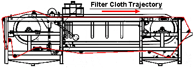
The following animation shows the operation of a belt filter and its components:
|
Move mouse pointer over the menu to view the components
|
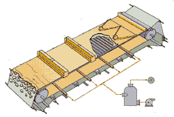
The filter consists of the following components and subassemblies:
The Drainage Belt
An endless rubber belt with traversing grooves drains the filtrate towards holes positioned along the belt. The sides of the belt have elastic rubber curbs that contain the incoming slurry and then the cake as it moves towards the discharge end. Synthetic heavy duty polyester plies are encapsulated in the rubber part below the grooves serve to withstand the longitudinal stresses to which the belt is subjected during its travel.
Drainage belts are available in 2, 3 and 4.2 meter widths and thicknesses of 28, 32 and 39 mm. The belts may be supplied in SBR or EPDM rubbers and both are elastomers characterized by a wide range of applications.
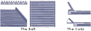
The weight of a 3 m wide belt is 125 Kg/m and this is the heaviest single component to be considered for the design of the hoisting facilities.
|
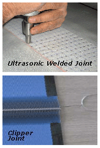
The Filter Cloth The filter cloth retains the cake and moves together with the belt. Nowadays, with some exceptions, they are made from synthetic materials such as polypropylene or polyester with monofilament or multifilament yarns and with sophisticated weaves and layers. The images on the right show an ultrasonically welded joint and a clipper joint of the cloth ends. With clipper joints, as may be seen on the right, it is necessary to thread multifilament strings across the entire cloth width to retain the fines from passing through to the filtrate. The entire subject of filter cloth and its selection will be discussed in a separate section that was not yet constructed. |
|
|
The Vacuum Box and Wear Belts
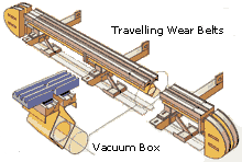
A vacuum box below the belt that is mounted along the filter and collects the filtrate through a manifold to the receivers. The box at its topside has two lips covered with low friction synthetic strip liners that seal through intermediate wear belts between the bottom side of the belt and the surface of the strips. Since the belt is the most expensive part of the filter these endless narrow belts serve as a sacrificial component that takes the wear between the surfaces, protects the rubber belt and secures against vacuum leaks.
The Vacuum Box Lowering Mechanism
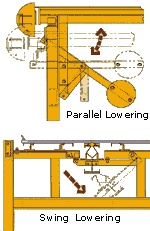 |
A special mechanism allows parallel lowering or swinging of the vacuum box for cleaning from fines that may have settled inside. The mechanism is designed to accurately seal between the underside of the main belt and the two narrow wear belts that move together along the slide strips attached to the top shoulders of the vacuum box.
|
|
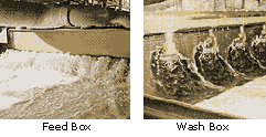
The Feed, Wash Boxes and Spray Manifolds A feed box and one or more wash boxes are mounted over the filter and designed to distribute evenly the slurry and wash water across the belt.
|
Spray washing as shown in the clip is also used quite often.
|
The Cake Discharge End
To watch the discharging cake please play the clip below:
|
Once the belt reaches the end of the vacuum box the cake drying portion of the cycle terminates and the cloth leaves the rubber belt. The cloth continues moving, changes direction over the discharge roll and the cake drops through a chute for further handling.
|
The Belt Supporting Deck
A deck attached to the frame and mounted underneath the belt is designed to support the heavy rubber belt and the cake load. The friction between the surfaces is reduced by injecting water for lubrication and blowing air that floats the belt or by a moving floor constructed of narrow endless belts that move together with the main rubber belt.
|
|
The Cloth Tracking Mechanism
A pneumatic or electrical tracking mechanism controls the filter cloth from slipping sideways by guiding it to the left or to the right.
There are several types of mechanisms but the following are very common:
-
Two pairs of rolls that pinch the cloth alternatively and are positioned on both sides.
-
A roll is that spans across the cloth, is hinged at one end and swings forwards or backwards on the other end.
Selection Criteria
Horizontal Belt Filters are selected in the following cases:
-
For solids that are fast settling and cannot be kept as a homogenous slurry in bottom or side feed filters such as Drum or Disc Filters.
-
When long drying time is required to reach asymptotic moisture in the cake. On , for example, the ratio of dry to form cannot normally exceed 1.5 since it is determined by its geometry and the number of circumferential compartments.
-
When very short cycle times are required for fast dewatering cakes such as phosphate slurry.
-
If a clear filtrate is required right from the start it is good practice to form a thin heel that serves as filter medium over the exposed cloth. This is done by either a "cloudy port outlet" that is recirculated or, if solids are settling fast, by allocating the first 20-30 cm to act as a "sedimentation pool" prior to entering the vacuum zone.
-
When intensive cake washing is required since belt filters make it possible to apply counter-current washing. On Drum Filters, for example, the time available for washing is rather limited due to its geometry.
-
When cakes tend to crack under vacuum measures such as a flapper, compression blanket or pressure roll may assist in sealing the cracks thus avoiding loss of vacuum. When such measures are used it is necessary to make sure that the belt supporting system can take these extra vertical loads.
-
When scale formation due to flash evaporation is a problem or filtrate temperature must be maintained a vacuum box steam jacketing may be provided.
-
When the cake tends to clog the cloth its continuous removal after cake discharge enables dislodging of particles by thorough washing of the cloth on both sides with high impact nozzles.
Maintenance
Horizontal Belt Filters are designed nowadays to meet a wide range of process requirements many of which are subjecting its components to severe and demanding conditions. Modern filters run at high speeds, handle thick and heavy cakes, operate at high temperatures and often in an unfriendly environment hence, they are of a sturdy design and made from sophisticated materials of construction.
The main points to observe are:
-
Evidence of cracks in the rubber belt may cause separation of the plies which are encapsulated between the rubber layers. This weakens the belt and should be repaired on site without delay.
-
The shrouds on both sides of the belt are subjected to high tension while going over the head and tail pulleys. Their duty is to contain the incoming feed and if the edges tear slurry may pour all over so inspection and their repair is essential.
-
The vacuum box is hinged and swings to one side so as to enable the periodical cleaning of its internals from settled fines. The repositioning of the box is one of the main reasons for loss of vacuum and special care must be taken to seal the box's anti-friction liners against the sacrificial wear belts and the bottom side of the main belt.
-
The endless wear belts must be inspected to ensure that they are in good condition otherwise the main belt may be damaged. Likewise, the wear belts should be checked if they seal properly between the stationary vacuum box and the moving belt.
-
The life of the belt and the main drive depend largely on the water lubrication between the surfaces of the moving and stationary parts hence, the tubes leading to those parts must be kept clean.
-
It is recommended that the alignment of the filter is inspected from time to time. This applies mainly to large filters since misalignment due to differential settling of the building foundations during the first years after start-up or any other reason may cause the following:
-
Along the filter, difficulties may arise in sealing the long and segmented vacuum box.
-
Across the filter, the thickness of the cake may taper in one direction causing uneven cake washing. The alignment across the filter is particularly important for thin cakes since a 0.5% slope on a 2 meter wide belt and a 20 mm cake reduces cake thickness on one side from 20 to 10 mm.
-


